Article: Using Embedded Linux in a High Speed Gated Intensified Camera
Jan 9, 2002 — by LinuxDevices Staff — from the LinuxDevices Archive — 51 viewsElphel, Inc. has used Embedded Linux in the design of a High Speed Gated Intensified Camera. The device combines a fast gated micro-channel plate (MCP) image intensifier, a CMOS image sensor, and an embedded computer based on an Axis Communications ETRAX RISC processor running Embedded Linux. These three ingredients made it possible to create an extremely compact (1.5 x 1.5 x 5.5 in.), ultra-fast (10 ns exposure, +/- 0.8 ns jitter) camera module that does not require a framegrabber or special software to operate — a standard 100Mbit Ethernet connection and a web browser are sufficient.
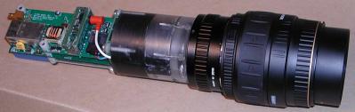
The Model 303 High Speed Gated Intensified Camera
Such cameras can be used individually if only a single snapshot of a fast event is needed, or if the moving object is bright on a dark background so multiple-exposure capability may be utilized, but the main application of these camera modules is as a multi-channel camera. That type of system consists of several cameras (usually one per frame), optical beam splitter(s), and additional electronics to sequence cameras triggering and multiplexing their outputs. When using Elphel modules, standard Ethernet hubs and N-way input trigger splitters can do the job, since each camera has it's own programmable sequencer. Also, as a result, extending the data link to the camera and converting it to fiberoptic is very simple and inexpensive, since regular copper-to-fiberoptic Ethernet converters are used.
What is a “gated intensified camera”?
This term refers to a class of ultra-fast cameras, with exposure times in the nanosecond range. “Intensified” comes from image intensifiers — vacuum tubes similar to those for the nigh-vision devices. “Gated” means those tubes (in contrast to night-vision applications) are used as shutters by applying fast electrical pulses to the control electrodes.
Most such cameras can only make a single snapshot of an object, requiring that multiple cameras (one per frame) be used when making even the shortest movies. This is due to two reasons. First, advancing even a “digital film” or reading out information from the image sensor takes time much longer than the exposure time. Even the fastest CMOS sensors with small readout window settings are limited to tens of thousands frames per second (fps), not a hundred million. The second reason is the long afterglow of the image intensifier output screen, which is in the millisecond range for high efficiency phosphors.
Actually, there are some tricks which are used to increase the number of frames captured per camera. One works with standard CCD chips used in video cameras, which all have “electronic shutters”. This function requires extra analog frame memory which (when using external shutter — image intensifier) can be used to capture two frames in a (relatively) fast sequence before the readout process can take place. “Relatively” means about 1 microsecond — still much longer than 10 nanoseconds, but for applications that require 10,000,000 fps (100ns inter-frame) and having 10 cameras this trick allows an increase in the total number of frames captured to 20 (each camera captures 2 frames 1 microsecond apart) and cust the per-frame cost to half. This is rather important for systems that usually have a price tag well above a hundred thousand dollars.
These tricks also require fast phosphors, which unfortunately are much less efficient than slow ones, with the result that image sensors/readout electronics need to be more sensitive. It is also possible to create (and some actually do exist) image sensors that can hold more than two frames — but this comes at a price of lower spatial resolution (less pixels/frame) and higher cost for specialized chips that are not manufactured in high volumes.
Why MCP?
MCP (micro-channel plate) image intensifiers use technology perfected for night vision applications. They have gains in the thousands to tens of thousands range — much higher than any non-MCP intensifiers — and gain is a very useful feature, because light is a very scarce commodity with several-nanosecond exposures. There is, for example, a million times less light in these exposure ranges as compared with regular still or video camera applications with several-millisecond exposures.
Another important benefit of MCP image intensifiers is that they usually only need a couple hundred volts to gate them, compared to the thousands needed to control other types of intensifiers.
On the other hand, the main MCP disadvantages are lower resolution and dynamic range.
Why CMOS sensor?
Most gated intensified cameras use CCD sensors, with fiberoptic tapers glued directly to the chip surfaces. This provides more efficient coupling than lenses, if used for transferring an MCP output image to the sensor surface.
CMOS image sensors (as compared to CCD) are usually “cameras-on-a-chip”, with all analog circuitry hidden inside, requiring just single low-voltage power supply, accepting digital commands and generating digital output. Price for convenience — lower sensitivity and higher fixed-pattern noise — pixel-to-pixel variation of sensitivity and dark signal (pixel value when no light is applied). A detailed CCD/CMOS comparison is available online at Dalsa, a manufacturer that produces both types of sensors. In this particular sensor application where it is attached to the MCP image intensifier most of the CMOS image sensor weaknesses are not significant.
Modern MCPs produce enough light for use with CMOS imagers. “Enough” means that increasing sensor sensitivity will not produce additional information (because of the quantum nature of light detection on the MCP input) — similar to trying to increase contrast of a digital image when you already see brightness/color bands (steps) if the original image is too dim.
The limited dynamic range of CMOS digital outputs (usually 8-10 bits) perfectly matches (even slightly exceeds) that of the MCP.
The fixed-pattern noise of these sensors is masked by that of superposition of patterns of micro-channels in MCP, fibers in its output (fiberoptic) window, fibers in the coupling taper and pixels in a sensor chip. Note that fixed-pattern noise only looks nasty on the raw images; it is not a real (random) noise, and may be eliminated without any information loss by per-pixel calibration — a simple operation for a camera that has sufficient computational power and memory for storing an array of coefficients.
Designing the Embedded Computer
As explained above, ultra-fast cameras need an array of single-frame cameras to capture a short movie of an event. As the number of individual cameras grows so does the role of their reliable networking.
Another important requirement is simplicity of firmware development, since these devices target a rather limited market and will never achieve the really high-volume production that is needed to pay for software design.
A third initial condition for me was that I wanted to create a really smart and self-sufficient device in order to minimize the requirements from a host computer — in terms of both its hardware and software.
Finally, I wanted to avoid so-called “plug-and-play” software, because these words generally result in a need to email and call technical support and hear how I should try to uninstall and reinstall drivers to get things working. I have always disliked trying to find out why my company's systems were not working our customers' sites — had my hardware really failed, or had they just updated some (seemingly unrelated) software on their computers which were running a popular OS?
This last issue unambiguously told me the camera should run a web server. Internet technologies are the best de-facto “common denominator” for the different computers and operating systems.
I had watched my friend trying to install and run Windows CE, Embedded NT, and Linux on a PC/104 computer. It was then that I asked myself (I'm a “hardware guy” who has designed multiple embedded systems using different processors and programmed them using assembly language): what is the minimal hardware that is needed to support Ethernet networking, Linux, and can run a web server?
After a one-day Internet search and comparison, a decided in favor of the ETRAX 100LX system-on-chip manufactured by Axis Communications. As usual the first document to download was the “Programmer Manual”, which has description of assembler codes and instruction execution times — but this time, I never used this information.
Several weekends were enough to design the embedded computer hardware (not the MCP control — I created that later). I just “cut and pasted” from the detailed ETRAX development board documentation, available at Axis site, and added only my application-specific circuitry.
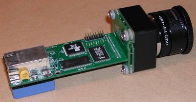
A view of the camera with MCP image intensifier removed, thus exposing the embedded computer circuitry — note that it is still a functioning network camera running a Linux-based webserver
In June 2001, I took a two-week vacation and asked my friend to install Linux on my home computer. At that point I had zero experience with Linux and didn't even know what “ls” meant.
Within two weeks, I was able to get jpeg images. And I fell in love with Linux. I could never have imagined how effective it would be to cut-and-paste pieces of software made by others, and how easy it would be to get in and modify it. I'm not sure how much of this is due to Linux itself, and how much is the result of an excellent product made by Axis and the support I've gotten from Mikael Starvik. Perhaps these are interrelated matters?
Are fast cameras required only for capturing fast events?
It is rather obvious that fast cameras are needed to capture fast phenomena — capturing explosions, ballistic tests, plasma studies, and lightning bolts.
There are also many other interesting applications not directly related fast events, such as very sensitive remote analysis using laser induced fluorescence (LIF) — images are captured some time after the object was illuminated by the short laser pulse. Another interesting application is that of looking through muddy water or just through heavy snow at night when headlights do not help (info); also, Flash LADAR technology — fast laser illumination and gated image capturing is used to capture 3-d information.
It is possible, for example, to put on the same rotating platform a laser, gated camera and second non-gated color one. Such a system is suitable for automatically building a 3-d model of the scene around the camera — the first camera is used to get the 3-d data, and the second, apply textures.
TODO: increase camera frame rate
The Model 303 gated intensified camera module is intended to be used for high speed photography. In these applications, the maximal readout frame rate of a module is not terribly important. In any case, it can capture just one frame of an event — so it works as a still camera. Live video mode is useful mostly for preliminary pointing, focusing, and adjusting gain. The current version of the camera uses software JPEG compression, and it takes up to several seconds to process a full 1288×1032 frame in high quality mode (without compression, frame rate is limited by the Fast Ethernet bandwidth).
Another area that can benefit from a high-sensitivity compact programmable network camera is that of night vision / security applications, but this definitely requires higher frame rates — which calls for hardware compression. Also, the need to compensate for fixed-pattern noise requires some that DSP functions be performed prior to compression at “hardware” speeds.
I am therefore looking forward to building a faster camera that will not be bigger. It will probably utilize two (not yet available) components: the new ETRAX 100LX Multi Chip Module (MCM) from Axis Communications, and the ADV-JP2000 JPEG-2000 compressor from Analog Devices. The smaller amount of SDRAM in the new ETRAX 100LX MCM as compared with the current camera is not a problem, since I will need to have separate raw frame/calibration coefficient memory, so the MCM's internal 8MB will be free of big image arrays. DSP functions for fixed-pattern noise elimination will likely be implemented on QuickLogic FPGA using look-up tables for multiplication.

NOTE: A version of this article translated into Russian is available here.
This article was originally published on LinuxDevices.com and has been donated to the open source community by QuinStreet Inc. Please visit LinuxToday.com for up-to-date news and articles about Linux and open source.