ELJonline: Embedded Video Capture on a Budget
May 1, 2001 — by LinuxDevices Staff — from the LinuxDevices Archive — viewsNeed to add video capture to your PC/104 system? Use an ISA board and save a bundle.
Embedded video capture is functionality required in some instances and just plain fun in others. Unfortunately, there is no such thing as PCMCIA-supported video capture for Linux, nor is there support yet for USB video capture devices. Frame grabbers in embedded form factors (like PC/104 or PC/104+) are pricey items, ranging from several hundreds to over a thousand dollars! These prices may be out of many budget ranges, particularly those of an experimenter or hobbyist.
Luckily, embedded frame grabbing with Linux doesn't have to be expensive. Linux drivers (and in some cases, kernel support) already exist for a number of conventional frame grabbers. The hardware is the sticking point, but we'll soon see how to handle that without emptying your wallet.
How do we do it? We fit a square peg into a round hole. The square peg is a conventional, inexpensive ISA frame grabber. The round hole we make it fit is the PC/104 bus.
A 16-bit PC/104 frame grabber and a 16-bit ISA frame grabber are very different looking beasts, but they are more similar than appearances would lead you to believe. The PC/104 bus (with a few small exceptions) is identical to the ISA bus — it's just a different shape. By creating an adaptor to connect an ISA frame grabber to a PC/104 connector, we can have an effective, economical frame-grabbing solution for our embedded Linux system.
The greatest advantages of this method are low cost and availability of materials. No special or esoteric parts are required to implement this solution.
The disadvantages are complexity (compared to buying a ready-made PC/104 frame grabber) and size. An ISA frame grabber is approximately twice the size of its PC/104 counterpart. Also, the single video input of most ISA frame grabbers may be a concern, depending on your application. An integrated video switcher is a common feature in embedded frame grabbers.
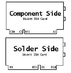
Before we go further, it is important to understand the signals present on the PC/104 and ISA buses. Figure 1 is a conventional ISA card layout. Note signal groups are labelled A, B, C and D.
 Figure 1. ISA Bus Signals
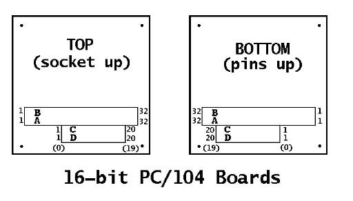
Figure 2 is the layout of a 16-bit PC/104 card. Note the same A, B, C and D signal groups.

Figure 2. PC/104 Signals
The first difference you will probably notice (other than the different form factors) is that the groups A, B, C and D do not have the same number of signals. ISA rows A and B have 31 pins, whereas the PC/104 connector has 32 pins in the same rows. Likewise, ISA rows C and D have 18 pins each, compared to 20 on the PC/104 card. Don't worry, the extra pins really are extra — we won't be hooking up all of them.
The second difference between the ISA and PC/104 bus is not as obvious. It has to do with the electrical specifications of some of the pins. PC/104 bus signals have reduced drive requirements on most of the lines. Specifically, /MEMCS16, /IOCS16, /MASTER and /ENDXFR (SRDY) must be driven with devices capable of handling 20mA of sink current, but all other signals need only 4mA of sink. This difference may not be significant for your application, but you should be aware of it.
There are two ways to solve the problem of connecting an ISA frame grabber to a PC/104 system. You can make an adaptor or purchase one. Sources for adaptors are listed later in this article, but I encourage you to make your own, as many commercial adaptors are bulky and intended for testing purposes only.
To get our ISA frame grabber working with our embedded system, we need the following:
- Embedded system with 16-bit PC/104 connector, also +5V and +12V power supply
- Linux-supported 16-bit ISA frame grabber
- 16-bit ISA slot (to hold the ISA card)
- 40 and 64 conductor ribbon cable and IDC sockets
- 40 and 64 row dual row pin headers
I personally use the MOPS/586 PC/104 board from Jumptec for my experimentation system. For the frame grabber, I selected a Winnov Videum VO 16-bit ISA card.
To construct the adaptor, begin by measuring out equal, appropriate lengths of 64 and 40 conductor ribbon cable. Be generous, since you can always cut some off later if it is too long, but you can never do the reverse. Less than eight inches may not leave enough slack to work with easily, and it may restrict placement of the frame-grabber card later. Separate, strip and tin the conductors on one end of the two ribbon cables. This is the end that will attach to the ISA connector.
Next, secure the unstripped ends of the ribbon cables into their matching IDC connectors and crimp the IDC connectors down. A special tool exists for crimping IDC connectors onto ribbon cables. The brave do-it-yourselfer may wish to improvise using vice grips and wooden slats.
Insert the dual row pin headers into the matching IDC sockets to turn them into male connectors that will plug into the top of the PC/104 socket. The 64-pin connector goes to the A and B socket, the 40-pin connector to the C and D socket.
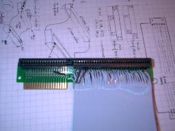
The final step is to connect the stripped and tinned conductors of the ribbon cables to the ISA socket. I used a small ISA riser (ISAR04) from Adex Electronics for ease of soldering, as it is basically an ISA slot on a small circuitboard with spare holes for all the signals. I also just happened to have it around. A piece of prototyping solderboard would do just as well (see Figure 3). You could also bite the bullet and solder directly to the ISA card itself.

Figure 3. Soldering to the ISA Slot
You'll recall that there are a different number of pins for each signal group between PC/104 and ISA. The pin mapping is explained below and is illustrated in Table 1.
Signal A1 (/IOCHK) on the PC/104 connector maps directly to signal A1 on the ISA card. Pin B1 (GND) on the PC/104 also maps directly to B1 on the ISA card. Signal groups A and B both match up, pin for pin, from signals A1 and B1 all the way to A31 and B31. The PC/104 bus has the extra pins A32 (GND) and B32 (GND), which do not have partners on the ISA card. It is okay to leave these unconnected, or you may tie them both to B1 (GND).
Connectors C and D are a little different. In Figure 2, the C and D signal groups have an alternate numbering; from C0 and D0 to C19 and D19 instead of C1 and D1 to C20 and D20, respectively. Why is this? Because the signals on C and D do not match up between the PC/104 connector and the ISA connector like they do for A and B. That is to say, C1 (/SBHE) on the ISA card does not correspond to the first pin for C (which is GND) on the PC/104 bus; it matches the second. The same is true for signal group D.
Therefore, if we renumber C and D for the PC/104 connector to start at C0 and D0 instead of C1 and D1, our life gets easier. C0 and D0 (which do not exist on the ISA card) remain unconnected, and we now have C1 and D1 though C18 and D18 matching C1 and D1 though to C18 and D18 on the ISA card, in the same way that groups A and B matched each other. The remaining pair of extra PC/104 pins (C19 and D19) also do not exist on the ISA card and may be left unconnected or tied to D18 (GND).
Care must be taken to correctly map the pins on the PC/104 connector to the proper signals on the ISA card. Remember to check and double-check with a continuity checker before soldering. Failure to connect the proper signals to the proper pins could damage your equipment.
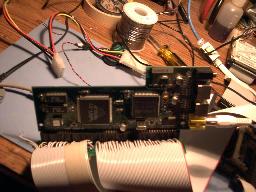
The ISA frame grabber is now ready to be attached to the adaptor. To save some space, you may wish to remove the ISA card's mounting bracket at this time.

Figure 4. The Finished Product
Once the frame grabber and adaptor are installed, boot up your embedded Linux system to install the appropriate drivers and make any necessary configurations. If you have chosen a Winnov Videum card as I have, drivers for Linux have been written by Bill Dirks and are available at www.thedirks.org/winnov.
A HOWTO has been written for the Videum card in Linux by Cliff Leong and is available at www.zerospin.com/ripley/doc/videum-howto.txt.
 About the author: Don Papp is a hardware designer and Linux enthusiast who enjoys robotics, poker and movies. He welcomes your comments or questions to [email protected] He is always interested in hearing about new projects and the uses to which people put their embedded systems.
Copyright © 2001 Specialized Systems Consultants, Inc. All rights reserved. Embedded Linux Journal Online is a cooperative project of Embedded Linux Journal and LinuxDevices.com.
This article was originally published on LinuxDevices.com and has been donated to the open source community by QuinStreet Inc. Please visit LinuxToday.com for up-to-date news and articles about Linux and open source.