Open source camera records geotagged video to SATA HDD
Jul 2, 2008 — by LinuxDevices Staff — from the LinuxDevices Archive — 77 viewsForeword: This paper describes a small, Utah-based company overcoming several hardware and software challenges to create an advanced Linux-based camera. Based on an 200MHz Axis ETRAX FS and an FPGA, Elphel's modular 353 camera, combined with several new expansion modules, can now capture geo-tagged video to CompactFlash or 1.8-inch drives.
The article was written by Andrey Filippov, a Russian physicist who emigrated to the US in 1995, and founded Elphel six years later. This is Filippov's seventh whitepaper for LinuxDevices — the others are listed at the end.
Enjoy . . . !
by Andrey Filippov
Since last year's publication of Open source-based high-resolution cameras for Web developers, we at Elphel worked on several projects that add to the performance of our model 353-based camera. These projects encompass hardware, FPGA code, and software.
Hardware development was focused on adding the new extension boards to the camera. The only improvement on the camera main system board (10353) was the removal of the network boot button, a small pushbutton with a function similar to most such ball-point pressed buttons found on many devices — to restore/update the flash memory image or restore defaults if held pressed during power up. That tiny pushbutton sometimes got peeled off the board (when pressed too hard), and was inconvenient to use remotely or when camera was mounted inside external enclosure.
Replacement of the boot button
(A fragment of the 10353E circuit diagram — full version is available on Elphel Wiki)
In the new revision we use a small analog circuitry (the total footprint is even smaller than that of a pushbutton) that switches the system to the network boot mode if the power is applied several times with small intervals (up to ~5sec) between cycles. Being powered up for approximately 30 seconds (or left longer without power) resets the circuitry to the normal boot. As the power is provided through the network cable (cameras use IEEE802.3af Power over Ethernet), it is easy to “press” the virtual button remotely, either by manually inserting the other end of the cable several times, or by using a simple script to turn on/off power if using a manageable PoE switch.
Adding mass storage to the camera
Being limited by the 100Mbps Ethernet port available on the ETRAX FS CPU used in the camera, we were looking into using the IDE port of this processor to be able to record video data directly to a hard drive, or to CompactFlash cards in “True IDE” mode. We started with the 10349 board, trying different IDE connectors. Only a 1.8-inch drive with flex cable (“ZIF”-type) fit the small camera, all other cables (40/80 conductors for 3.5-inch or 44 conductors for the 2.5-inch disks) being too bulky. An obvious solution would be to use an IDE-to-SATA bridge chip, but here we ran into problems somewhat similar to the ones that free software developers see when developing drivers for the PC hardware: a lack of open documentation. There are multiple manufacturers who make IDE-SATA bridges, but I could not find datasheets that describe those chips, or even have a very minimum pinout diagram. All of them required signing an NDA (non-disclosure agreement) to get even this basic information, and that is not acceptable for Elphel, as we need at least the pinout of the chip to be able to include it in our circuit diagram that we release under GNU FDL and make available for download. And that pinout would be enough for us — the bridge is transparent, and does need special drivers that would rely on some proprietary information.
So after failing to get the documentation required to add an IDE-to-SATA bridge chip, I decided to investigate first if the commercially available IDE-to-SATA adapters would work with the ETRAX FS. I purchased all such adapters I could find on the Internet (some turned out to be duplicates), and found that they are based on four different bridge chips. All seem to work fine when connected directly to the ETRAX FS IDE port. I was expecting those chips to be functionally the same, but it was a surprise for me to find out that they all are pin-compatible — at least for most of the obvious pins, like four SATA signals, IDE, power, and the crystal. So I made a guess that they are identical, and used incomplete information found on the Internet for various chips — including a circuit diagram for a discontinued chip — in order to guess the pin-out.
That guess about pin-compatibility seemed to work, and the board designed with the SATA bridge chip ran fine without any additional tweaking, but I do not want to advertise the manufacturer of the particular chip we used in the first version of the 10369 board (anyway we may replace it in the future), so on the circuit diagram it is marked as “Generic SATA Bridge”.
Connecting Compact Flash cards
With the CF cards capacity going up and the prices going down (32GB were less expensive than 16GB a year ago), it would be very attractive to add connectors for such cards to the camera. I wrote “connectors” as the CF cards support “True IDE” mode and can be directly connected to the same IDE signals available from the ETRAX FS (3 signals need resistor termination). It seemed to be a really easy job, with the most challenging part being mechanically fitting the card(s) inside the camera enclosure. I did not want to increase the overall dimensions of the camera. That was solved using a riser board (103691) that allowed us to fit two CF cards inside our standard camera. It is also possible to attach a 1.8-inch drive with ZIF connector by using a different riser board (103692). And, we could make more such boards with different termination (i.e. 2.5-inch or 3.5-inch HDD).
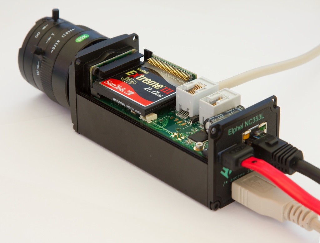
NC353L camera assembly with the 10369 interface board
and Compact Flash card installed
(Click to enlarge)
Mechanical challenges turned out to be not the only ones waiting for me when I worked on connecting the CF cards to the camera. These cards were hanging when the CPU tried to read them using DMA mode (and the card identified itself as supporting DMA mode). I tried to find the problem, and used all the tools I had. I added a bunch of printk's to the driver source, tried different speed settings for the DMA, and finally used an oscilloscope to spy on the signals between the CF card and the CPU. What I found was that the card did actually send the data using DMA mode, but always only for two “sectors” (1024 bytes total), regardless of the number of blocks to transfer written to the corresponding register. Then it silently hung, without activating an IRQ line, even if it was asked to transfer just a single block. And the CPU was relying on that interrupt to continue with the processing of the data read from the CF card. Careful examination of the data on the IDE bus did not reveal any problems (I was expecting something specific to the ETRAX). The same CF card with the DMA mode disabled in the driver worked fine (but slower, of course), as did the IDE hard drive (or SATA through the bridge) with DMA enabled. Googling the issue showed that I'm not the first to have problems with CF cards and DMA. The driver itself had a blacklist for some of the devices that caused problems.
Next thing was to try different CF cards, and see if the problem persisted. I went to newegg.com and ordered nine more, choosing various brands and models. Only one of them, the Sandisk Extreme(R) III 2.0GB, worked. All others exhibited the same behavior described above. So I opened up the first card (QMemory 16GB) to see what kind of a controller chip they use. It turned out to be a Silicon Motion SM222TF. I saw the same problem in a Transcend 32GB card with a SM223TF controller. Exhausting all my ideas, I emailed to the customer support address of the chip manufacturer. At first they were trying to redirect me to the card manufacturer, then admitted that “we have some firmware issue with DMA mode in the past, and I am not sure if the card you have can support DMA mode properly.” But when I sent the detailed description of the behavior of the chip, asking if there is any way to mitigate the problem, they just stopped responding to my emails completely.
I still think it is possible to make the cards based on these chips work in the DMA mode without any possible secret commands or other tricks (if they actually exist), by modifying the behavior of the driver. Make it limit the transfers to just 2 blocks (rather easy — I already tried that). And, more importantly, remove the dependency on the IRQ generated at the end of the transfer, by using the internally (in ETRAX or system DMA controller) generated interrupt when the required number of bytes were transferred — however, that is a much larger driver modification that I did not have a chance to work on. It should be applicable to other architectures too, not just to the ETRAX FS IDE controller. This is my excuse for going into such detail describing the nature of the CF cards DMA problems.
USB as a system bus
The ETRAX FS, like many other microcontrollers, has an on-chip USB host controller that greatly simplifies attaching various peripherals to the camera. Those can be commercial devices like flash memories, WiFi adapters, sound cards, Bluetooth adapters, or cellular modems. Of course, it only works for devices that have open source drivers, as wrappers for proprietary x86 drivers would be of no help on the CRIS architecture. In addition to the off-the-shelf devices, it is now rather easy to implement a custom device with a USB interface. There are multiple adapter chips available (i.e. USB-to-RS-232), as well as programmable microcontrollers that have USB capabilities. Atmel makes one with just a 5×5 mm footprint. There are also in-between products on the market — board-level systems with USB interfaces.
The 10369 board has a USB hub with four downstream ports (upstream being connected to the ETRAX through the inter-board connector). One of the ports is intended to be used for external USB devices; the other three, for internal “granddaughter” boards. Standard USB connectors and cables (even micro) are too large for use inside the camera, so the 10369 board has 0.5mm pitch 10-pin flex cable connectors. In addition to four needed for the USB, these (internal) connectors have 3.3V power, and four general purpose LVTTL I/Os routed to the FPGA on the main camera board (two of which are common for all connectors, and are currently programmed as i2c bus). The external USB connector is mounted on the back panel and connected to the 10369 board with a flex cable, so any of the internal connectors can be converted to external if more connector holes are made in the camera enclosure.
The USB hub on the 10369 board is designed to support USB 2.0, while ETRAX has only slower 1.1 interface. So, this feature will have to wait for the next generation of the camera system board that will support USB 2.0 and Gigabit Ethernet. That camera is not ready yet, but it will be described in the next year's article.
Inter-camera synchronization
The Model 353 camera in standard complectation uses a five-megapixel Micron (now Aptina) CMOS image sensor with an electronic rolling shutter (ERS) that uses fewer transistors per pixel than a snapshot shutter, but the result is that each scan line is exposed at different time. It is still important to have precise synchronization between multiple cameras or camera modules in a multi-camera system, and the sensors have a provision to start exposure+readout synchronized to an external signal.
Stereo vision is one such application. Two cameras with a horizontal stereo base can use ERS sensors if both sensors scan the same line at the same time and the sensors are mechanically adjusted to minimize vertical shift (or tilt) between the images, so each 3D point is exposed in both sensors at approximately the same time (difference is less than exposure time).
Another application that benefits from inter-camera synchronization is multi-camera systems for panoramic imagery. Knowing the precise timing of each image line acquisition helps when stitching the individual images into a panorama.
The 10369 boards have two individual sets of I/Os for the synchronization of several cameras:
- Small 4-pin flex cable connectors to interconnect multiple camera boards in a common enclosure
- Modular RJ-14 4-pin connectors for synchronizing multiple individual cameras
Each of the two channels has bi-directional opto-isolated I/O's and a non-isolated high current driver that can trigger multiple cameras. The FPGA code includes a programmable generator that can control the synchronization output drivers, and a programmable input delay generator driven by the selected opto-isolated inputs so each sensor can be triggered with a specified delay from the common for-multiple-cameras trigger. There is also circuitry to drive sensor trigger input.
The same FPGA module can be used in a single camera configuration to provide precise control over the frame rate. The period of the free running sensor is defined as a product of the number of lines by the number of pixels in a line (including invisible margins) by a pixel period, so there are some restrictions on the period that can be programmed. This triggered mode of sensor operation also simplifies alternating the exposure time between consecutive frames (i.e. for hard drive recorder (HDR) applications). In a free-running ERS mode, exposure overlaps between frames and it is not possible to control it independently for each frame.
There are more functions implemented in the 10369 board, such as RS-232 port, thermometer, clock/calendar. Details (as well as circuit diagram, PCB layout and BOM) are available on the wiki page.
Connecting USB peripherals
As we planned to geotag the images, we needed GPS, and that was easy. There are plenty of devices on the market that have a USB interface, and we tried Garmin GPS 18 USB. It is absolutely the same as running this device attached to a laptop running GNU/Linux: you enable kernel support of Garmin devices (usb-serial.c, garmin_gps.c ), and install an application to read the data. And as all the camera software comes with the complete source that is sufficient to rebuild the camera image (during installation it will download non-Elphel free software from respective sources), you do not need to be a member of Elphel team to add support for other devices. The source code and installation scripts are available on the Elphel project at Sourceforge as tarballs, in CVS repository, and each camera file system. The installation script includes all the source files in the flash image, so each camera internally has the source of the software it is running even in the case software was modified — a nice feature for troubleshooting problems, not just bringing GPL compliance to a higher level.
The second device we considered was a digital compass with accelerometers for measuring roll/pitch of the camera. It is useful to orient video in space or create your personal “Street View”-like images. Additionally it might be a step to geo-locate the objects in the camera view, not just the camera itself. We used Ocean Server's OS5000-US, a 1-inch x 1-inch digital compass. It fit nicely inside the camera, attached with non-magnetic screws to the camera top cover. We just had to piggy-back the board with our 103693 adapter boards (without the large USB connector) and solder four USB wires directly between the 2 boards. Then, we connected the “sandwich” to the camera board with a flex jumper and added cp2101.c — support for the CP2101 chip (usb to RS232 converter used in OS5000) to the kernel.
Images and metadata in the camera software
Images acquired from the sensor are compressed in the FPGA and delivered to the large (19MB) circular buffer in the camera system memory using DMA, so once programmed video data can be transferred to the buffer without any software intervention. The FPGA still generates an interrupt after each frame acquired. This interrupt is used to activate applications that were blocked while waiting for the next frame available, as well as to initiate other support functions:
- Adjust exposure to compensate for the changing lighting conditions.
- Update data structures related to the frames acquired, including the frame metadata.
In most cases, metadata is provided to the applications as Exif headers attached to the images stored in the circular buffer by the hardware. Exif processing in the camera is designed to be flexible, so support of additional fields can be easily added. It starts with an XML file with a description of the tags and data types used, required field sizes (until regenerated, the Exif header size in the camera has a fixed size). This file is processed by the PHP script in the camera that generates the header template containing all data in the header that does not change between frames. That includes complete tags for the constant data that does not change during camera operation (i.e. camera software version), and all but the data itself for the variable tags. Later, when the frames are retrieved, the driver treats this template similar to format in a printf function. In addition to this template, the exif.php script also provides the Exif device driver with the data structure information — tag value and data length in bytes used for this tag. The driver does not interpret the data; it just stores data bytes written “to the tag” and uses it to fill the blanks in the template when requested. Additionally the tag sequence is provided, so the driver can later accept writes spanning several tags in a single write call (the camera is powered by only a 200MHz CPU, so performance issues are important).
The driver stores an array of Exif data structures (pure data to be combined with the template during output) — one element per image in the circular buffer, element with index 0 is reserved for “now”. Multiple sources write to the “now” structure, some from inside the kernel (i.e. exposure, time stamp), others from applications like the ones handling GPS or even the custom PHP scripts handling HTTP requests (i.e. changing image description while recording). When the frame interrupt happens, data from the “now” structure is copied to one in the array and the index is saved with the images so when the image is requested by one of the applications (image server, video streamer or video recorder), the metadata for that particular frame is retrieved. All writes to the “now” structure are atomic (interrupts are disabled), so writing multiple consecutive tags in a single write request guarantees that they will appear in the output all together.
When the Exif driver is enabled each application receives frames with the header containing metadata that can be read with most applications and such online services as Flickr (example) or Panoramio (example). If the camera detects GPS and/or compass during boot process, the related tags are included in the template; otherwise they are omitted. Unfortunately there are no Exif tags for roll and pitch of the camera, so we used a hack and encoded it as “Destination Latitude” for pitch and “Destination Longitude” for roll – this way the data is displayed by the applications.
These examples show geotagging of the individual frames. The camera tags each frame recorded — currently it is up to 2592×[email protected] fps or 1920×[email protected] — but we could not find any application that makes use of the geotagged video. It would be fun to develop one, for example to “play” the geo data on Google Maps, create a screen capture, and combine it with the actual video. I'm sure more video camera with GPS/compass data will be available soon, so such applications will have wider application than just for Elphel cameras. Meanwhile, we made the cameras to generate KML files in parallel with recording video. The frame rate is much slower (interval between frames is one second or more), but the result can be immediately displayed in Google Earth application.
Under Development
There are several projects currently under development at Elphel:
- Improving audio in the camera, supporting more USB adapters that can be used to record sound synchronized with the video
- FPGA code and the software to support 10359 FPGA-based camera extension board. Currently it is capable of simultaneous acquisition images from three sensors, storing them in the on-board memory and sending to the camera one at a time. We plan to add processing to the image data.
- Developing additional compression modes (based on JPEG) for efficient handling of the raw Bayer data from the sensor. There are now algorithms that result in very high quality restoration of the color images from the Bayer filter mosaic, but some are difficult to implement in the FPGA as they use image data rather far from the pixel to be interpolated, so in some cases it is easier to post-process the video after it was recorded. We used such an approach for a document scanning application. Currently, the FPGA in the camera can process 80MPix/sec in this mode, so the frame rate for the 5-megapixel sensor is limited by the sensor itself — it is 15fps. The coming software release 7.2 will have this higher frame rate available.
- Implementation of command queuing in the FPGA. In the existent firmware, once the image sensor and the FPGA are programmed, the video data will go to the buffer in the system memory automatically without software overhead. But, it all breaks up when you need to change some of the acquisition parameters, either sensor settings or the FPGA ones. In many cases, the acquisition process has to be stopped and re-programmed, or else the “broken” frames are output or the compressor may go completely out of sync with the sensor. Command queues in the FPGA allow scheduling sequences of commands (separately i2c ones for the sensor and direct ones to the FPGA internal registers) are activated after the corresponding frame sync pulse, up to six frames later than they were written to the queue. That allows coordinated reprogramming of the sensor and different FPGA modules, compensating for any latencies in the image acquisition and compression chain, and the “broken” frames are avoided. Additionally it reduces real-time requirements to the software, giving it more time before it has to take action. These features will also be available in the software release 7.2
 About the author — Andrey N. Filippov has over 25 years of experience in embedded systems design. Since graduation from the Moscow Institute for Physics and Technology in 1978, he worked for the General Physics Institute (Moscow, Russia) in the area of high-speed, high-resolution mixed signal design, application of PLDs and FPGAs, and microprocessor-based embedded system hardware and software design. Andrey holds a PhD in Physics from the Moscow Institute for Physics and Technology. In 1995 Andrey moved to the United States and after working for Cordin Company (Salt Lake City, Utah) for six years, in 2001 he started Elphel, Inc., dedicated to doing business in emerging field of open systems based on free (GNU/GPL) software and open hardware. This photo of the author was made using a Model 303 High Speed Gated Intensified Camera.
More papers by Andrey Filippov:
- Open source-based high-resolution cameras for Web developers
- AJAX, LAMP, and liveDVD for a Linux-based camera
- Building an Ogg Theora camera using an FPGA and embedded Linux
- How to use free software in FPGA embedded designs
- Using Embedded Linux in a reconfigurable high-res network camera
- Using Embedded Linux in a High Speed Gated Intensified Camera
This article was originally published on LinuxDevices.com and has been donated to the open source community by QuinStreet Inc. Please visit LinuxToday.com for up-to-date news and articles about Linux and open source.